

 Introduction
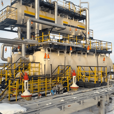
Oil/Water/Gas separator tanks, commonly referred to as separators, are vital components in many processes, specifically oil & gas processes. Separators play a crucial role in the efficient separation of oil, water, gases, vapors, as well as contaminants. They serve as an important protective, ensuring compliance with environmental regulations and maintaining operational integrity. The contents that enter these separators originate from wellheads and various stages of fluid processing and refining processes. While separators are instrumental in managing these fluids and gasses, ensuring their optimal performance requires constant monitoring, particularly regarding pressure levels.
Ensuring the integrity and safety of separators is crucial, and pressure protection plays a critical role in achieving this goal. Inadequate pressure monitoring can result in severe consequences, including environmental contamination, structural damage, and risks to the safety of personnel and nearby equipment. To mitigate these unwanted or dangerous situations, Safety Instrumented Systems (SIS) are routinely applied. This whitepaper covers the significant importance of pressure protection for separators.
Separator Pressure Protection
Pressure protection within separators is critical for maintaining operational efficiency, environmental compliance, and personnel & equipment safety. Neglecting pressure monitoring can lead to severe consequences, especially when pressure levels exceed safe limits. High pressure in separators can result in structural damage, risking the structural integrity of the separator causing leaks or ruptures which could leak flammable vapors and gases causing environmental contamination. A worst-case scenario would include a potential explosion caused by the leaked gases encountering an ignition source such as a flame or spark.
Role of Logic Solvers in Pressure Protection of Separators
A Safety Instrumented System consists of one or more Safety Instrumented Functions (SIFs) that work independently or together to take processes to a safe or desirable state. A typical SIF would involve a sensor such as a pressure transmitter, a logic solver that reads the process variable signal from the sensor, and an actuator or final element that is triggered by the logic solver to take the process to a safe state. For upstream oil and gas locations that only have a single separator with one pressure signal to monitor, single-loop logic solvers like alarm trips have been used to provide emergency shutdown in case of excessive pressure readings. Larger logic solvers such as Safety Programmable Logic Controllers (PLCs) are normally used when there are many points or loops involved in a SIS and come at a hefty price tag. Due to the limited number of safety loops at an upstream wellhead location where separators are found, this would be overkill. However, a new type of logic solver, the SLA Multiloop Safety Logic Solver, has been introduced which can handle up to three SIF loops with 17 onboard I/O points. Unlike a simple single-loop logic solver, the SLA has voting and logic capability similar to a traditional safety PLC, but without complex programming. The SLA implements math with Excel-like formulas and voting logic through checkboxes in a license-free FDT/DTM programming environment as opposed to complex safety PLC programming. This offers a more cost-effective and efficient logic solver solution where more than one separator pressure or loop needs to be
monitored.
In the following application examples, we will highlight the use of a single STA Single- Loop Logic Solver on a single separator SIF and a SLA Multiloop Logic Solver on multiple separator SIFs. For both application examples, we will assume that all SIFs need to meet SIL 2. Several factors must be assessed when determining if your chosen equipment within your SIF will meet your SIL requirement. As seen in the chart below, to meet SIL 2 your SIF must be available to take your process to a safe state at least 99% of the time, in a low demand rate. Most logic solvers today are Type B devices, considered complex by IEC 61508 since they contain complex components that have failure rates that are difficult to predict and firmware. As such, it is common for these logic solvers to have internal diagnostics that continuously monitor their health and provide a relay contact if any internal failure or anomaly occurs. Without such internal checks or diagnostic coverage, the logic solver may not meet the required or expected equipment Safety Failure Fraction (SFF) for the SIF.
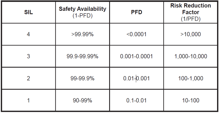 Figure 1: SIL Levels as defined by IEC61508/IEC61511
Separator Pressure Application Example
To demonstrate how the STA and SLA are applied as logic solvers for separator pressure protection, we will use the following application details.
There are three separators located at the site that need safety protection applied. Each separator has a pressure transmitter attached to a logic solver, which sends pressure readings via a 4-20mA signal. When pressure in the separator reaches extremely high-pressure levels, this is considered a dangerous condition. To attain high integrity of the separator pressure SIF, the diagnostics of the logic solver shall be monitored
continuously. Should the logic solver experience any faults or separator pressure breach its high-pressure limit, a shutdown of the separator should take place.
All separator SIFs require that logic solvers be IEC 61508 certified and SIL 2 capable. Due to limited power supply and remote locations, the logic solver shall power the connected pressure transmitter and be suitable for outdoor installation and harsh environments.
Separator Pressure SIF Requirements
- Logic solvers used for each separator SIF must be IEC 61508 certified and SIL 2 capable.
- The logic solver must be able to provide power to the pressure transmitter on the separator.
- Outdoor installation location requires an ambient operating temperature range of -40 to 85°C.
- A High-Pressure alarm needs to be configured for shutdown initiation.
- Logic solver internal diagnostics/faults must be continuously monitored.
- Logic solver shall shutdown
STA as a Logic Solver in a Separator High-Pressure SIF
The STA Safety Trip Alarm is a single-loop logic solver that responds to potentially hazardous process conditions by providing emergency shutdown or early warning indication in an SIS. It is certified by exida® and is SIL 2/3 capable. The STA is pushbutton or PC-configured and has a local readout to show separator pressure. An auxiliary 24V power supply is available on the input terminals to provide power to the separator’s pressure transmitter.
The STA provides two process alarms and one fault relay output. Each alarm is tied to a failsafe SPDT relay output. The STA has a fault relay that is triggered if the internal diagnostics uncover any hardware or firmware faults. If any faults are detected, the fault relay will be engaged. As Figure 2 illustrates, the hi-pressure alarm relay output and the STA fault relay are physically wired in series with the shutdown circuit or final actuator. Since the STA process relays and fault relay are failsafe (de-energize to trip), the separator shutdown circuit will be initiated if there is a hi-pressure alarm, STA fault, or power loss to the STA.
Since the STA is a single-loop logic solver and only accepts one input, three STAs will need to be installed to handle each of the three separator SIFs. If the SIF needs to meet SIL 3, two STAs could be used as the logic solver element for each SIF in a 1oo2 voting scheme. This would require the process relays and fault relays of each STA to be wired in series to initiate the shutdown circuit. In addition, the sensors and final actuators should be assessed for their SIL 3 capabilities.
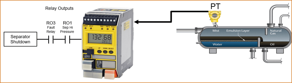 Figure 2: The STA utilized as a single loop logic solver for each separator high-pressure SIF.
SLA as a Multiloop Logic Solver in Separator High-Pressure SIFs
The SLA is an exida-certified SIL 2/3 capable Multiloop Safety Logic Solver and Alarm that performs as a single or multiloop logic solver incorporating enhanced math, voting, and logic capability to act on potentially hazardous process conditions in a SIS. The SLA is an ideal logic solver for this application example given its SIL 2/3 capability and multiloop ability to handle up to three safety loops. The SLA accepts six analog inputs, four discrete inputs and includes auxiliary 24V power for connected transmitters. While redundant pressure sensors are not required for this specific application, the SLA could be configured to monitor two pressure inputs per separator with automatic failover capability, should one pressure sensor fail.
Unlike single-loop logic solvers that have limited alarm capabilities, the SLA includes 16 configurable internal alarms that can be assigned to any, or multiple, of the SLA’s four relay outputs. Voting scenarios can also be easily implemented with any combination of internal alarms, discrete inputs, internal logic statements, faults, or even relay outputs. This along with the SLA’s math and logic capability, provides an extensive array of alarming or safety shutdown schemes.
As was required with the STA single loop logic solver, the logic solver’s faults must be continuously monitored to provide the desired safety availability. Fortunately, the SLA has the ability to internally monitor the status of the fault relay and use it in any voting logic, equation, or alarming scheme necessary. High-pressure internal alarms are configured in the SLA for each of the three separators. One additional internal alarm is configured to monitor the SLA’s fault relay should any faults or failures be detected. Now that four internal alarms have been configured, each of the three separator SIFs can utilize a dedicated failsafe relay output to initiate high-pressure separator shutdown.
As illustrated in Figure 3, relay outputs 1-3 use voting logic within the SLA to determine if a high-pressure condition or SLA fault has been detected. If either scenario exists, the respective failsafe relay output is triggered, and separator shutdown follows. While three independent single-loop logic solvers were required in the prior example, the multiloop and internal voting capability within the SLA allows for one logic solver to be used for all three high-pressure separator SIFs, thus reducing cost, maintenance, and wiring complexity.
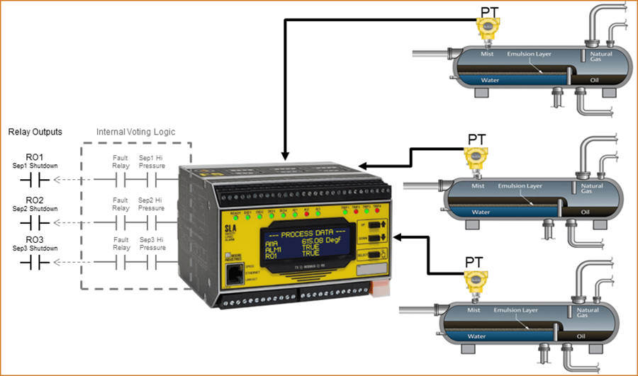 Figure 3: The SLA is used as a multiloop SIS logic solver handling three SIFs, one for each separator. Internal voting logic is used in the SLA to initiate a separator shutdown if either high pressure is reached, or a fault is detected with the SLA.
The SLA was designed to be more capable, powerful, and flexible than single-loop logic solvers, but easy to program. While safety PLCs can certainly handle much higher point counts than the SLA, many safety practitioners have applications that require just a few loops or smaller point counts but don’t need or want the complexity of programming and maintaining a safety PLC. To alleviate these concerns, all SLA configuration is accomplished in an open and royalty-free DTM/FDT environment. FDT programming environments such as PACTware are free to end users and offer simple and straightforward screens for device configuration. To demonstrate the SLA’s ease of configuration for this application example, we have provided a few PACTware screenshot examples below.
To configure the SLA as a logic solver for three separators, PACTware is used to create the high-pressure alarms and voting logic required to initiate safety shutdown. Outlined below are the key configuration requirements and associated PACTware screenshots demonstrating the SLA’s ease of programming and setup.
SLA Key Configuration Requirements for High-Pressure SIF
Required separator alarms:
Separator 1
• Create ALM1 = Hi Pressure Alarm
Separator 2
• Create ALM2 = Hi Pressure Alarm
Separator 3
• Create ALM3 = Hi Pressure Alarm
SLA Fault Alarm
• Create ALM4 = Set Alarm Type as Discrete, 1oo1 Voting, Source 1 is RO4 (SLA Fault Alarm)
Required separator shutdown outputs:
Separator 1
• Create RO1 = 1oo2 voting on ALM1 (High Pressure) or ALM4 (SLA Fault Relay)
Separator 2
• Create RO2 = 1oo2 voting on ALM2 (High Pressure) or ALM4 (SLA Fault Relay)
Separator 3
• Create RO3 = 1oo2 voting on ALM3 (High Pressure) or ALM4 (SLA Fault Relay)
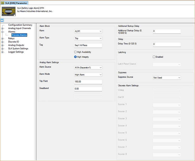 Figure 4: PACTware configuration screen depicting how each of the three separator high-pressure alarms would be configured in the SLA.
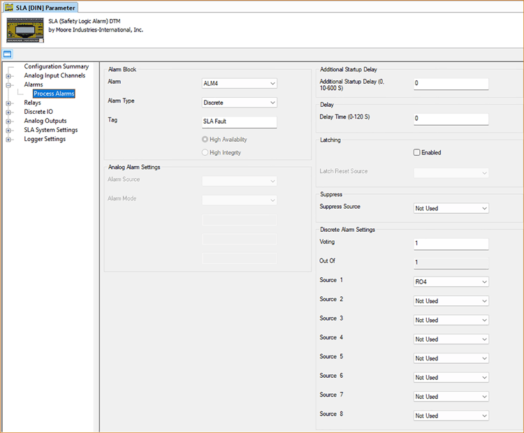 Figure 5: Alarm four configuration screen showing how the SLA Faults are assigned to an internal alarm, in this case to ALM4.
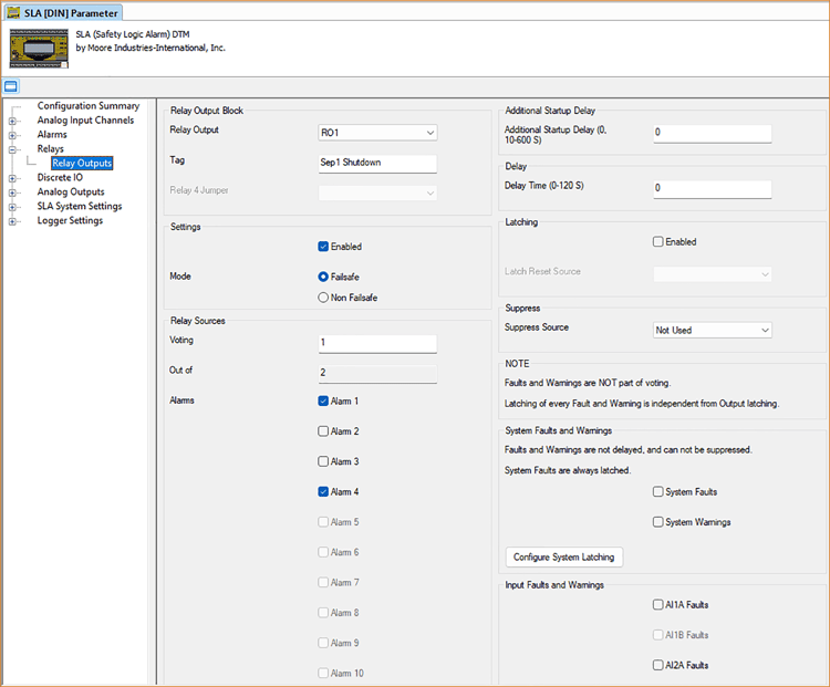 Figure 6: Relay output configuration screen demonstrating how relay outputs are assigned to each of the separator shutdown SIFs. This is where the simple 1oo2 voting logic is implemented to trigger a separator shutdown if either a high-pressure alarm exists or there is a fault detected with the SLA logic solver.
At a Glance Comparison of STA and SLA Logic Solvers
- The STA can handle only one SIF at a time, while the SLA can handle up to three SIFs.
- The SLA has easy-to-use voting logic capability, the STA does not have any voting capability.
- Both the STA and SLA are exida-approved and SIL 2/3 capable.
- The SLA can handle up to 16 alarms while the STA can only handle two alarms.
- The SLA includes an onboard read-only web server that allows all SLA parameters to be read with an off-the-shelf web browser. The STA includes no digital interface or output.
- The SLA accepts six analog inputs, while the STA accepts only one input.
- The SLA has four discrete input/output channels that could be used to suppress the shutdown circuits/alarms during process startup. The STA has no discrete input channels.
- The SLA has three analog outputs which can be used to retransmit the separator’s pressure readings to an auxiliary monitoring device, while the STA has only one analog output.
- The SLA analog outputs pass HART data when corresponding analog input channels are connected to HART devices allowing full access to connected field devices by HART hosts. The STA does not pass any HART data.
- The SLA has an onboard event logger that captures key data that can be exported to a .csv file, while the STA has no logging capabilities.
- The SLA supports read-only MODBUS/TCP and MODBUS RTU industrial protocols.
- The SLA has an intuitive equation/expression editor for math and logic functions that is easy to use, while the STA has no math or logic capability.
- Both SLA and STA support operating temperature ranges of -40 to 85°.
Conclusion
Neglecting to monitor separator pressure levels can result in serious consequences, such as damage to the separators’ structure, environmental contamination, and risks to those nearby. High pressure within the separators can cause leaks, ruptures, or even catastrophic explosions, which can have severe impacts on both operational efficiency and safety protocols. Therefore, it is essential to implement strong pressure protection measures, such as a Safety Instrumented System, to mitigate potential hazards and maintain optimal performance of the separators.
Logic solvers are critical components for ensuring the safety of separators, especially when it comes to Safety Instrumented Functions. While traditional single-loop logic solvers like the STA are successfully used, newer solutions like the SLA multiloop logic solver offer more advanced capabilities, particularly in applications that require monitoring of multiple separators.
The SLA is a logic solver that offers numerous advantages for separator applications. Unlike other single-loop logic solvers, the SLA can handle up to three safety loops simultaneously, making it more versatile and reducing the need for multiple logic solvers. With easy setup using PACTware software, easy-to-configure voting logic, and enhanced math capabilities, the SLA is an excellent solution for managing pressure protection in separators. By utilizing these advanced features of the SLA, operators can increase operational efficiency, reduce risks, and maintain safety standards with ease and confidence, without requiring more complex and expensive equipment commonly associated with Safety PLCs.
Download a copy of the White Paper